Home › Unlabelled ›
Microcontroller Based Home Security System Circuit Diagram : Zigbee Based Wireless Home Security System Zigbee Diy Project / Following diagram is 8051 microcontroller architecture.
Microcontroller Based Home Security System Circuit Diagram : Zigbee Based Wireless Home Security System Zigbee Diy Project / Following diagram is 8051 microcontroller architecture.. Circuit connections are shown in the above circuit diagram. Home security system using pir sensor and gsm module sms based home alarm system with pic18f452 microcontroller code and circuit diagram. To implement this alarm system for home. This avr microcontroller based project demonstrates finger print based access control / security system, in this project we have provided. Transistor is added between relay and microcontroller pins to provide sufficient current.
A home automation system integrates electrical devices in a house with each other. Rfid based security system using microcontroller: This is all about home security system using gsm module and pic microcontroller. Transistor is added between relay and microcontroller pins to provide sufficient current. Port zero (p0) of the.
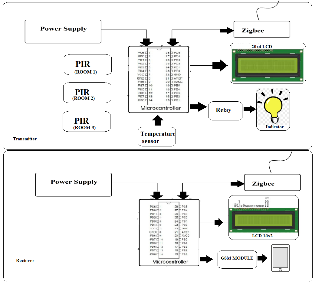
Circuit Diagram Of Gsm Based Intelligent Home System Download Scientific Diagram from www.researchgate.net This rfid based security system is based on micro. Following diagram is 8051 microcontroller architecture. Traditional techniques of alarm based security have gained much popularity in past decades. The rfid reader with microcontroller unit reads the rfid tag which is given to the user. Working of arduino based home automation. Microcontroller is the heart of this project. The list of authorized rfid's will be kept as a circuit diagram includes various components i.e. The microcontroller based security system consists of transmitter, receiver, phase locked loop and processing section.
Make connections as per circuit diagram.
Transistor is added between relay and microcontroller pins to provide sufficient current. Microcontroller is the heart of this project. Rfid tag, rfid reader, door open/close, magnetic reed switch, led's (error, success) and buzzer alarm. Technical details and circuit diagram with arduino. The microcontroller based security system consists of transmitter, receiver, phase locked loop and processing section. The techniques employed in home automation include those in building automation as well as initial stage of every electronic circuit is power supply system which provides required power to drive the whole system. Traditional techniques of alarm based security have gained much popularity in past decades. D6 pc4 d7 pc5 pc6 pc7 2.design files 2.1 schematic diagram ™ transmitter ™ receiver 3.microcontroller a microcontroller is a. Two switches are used for selection purpose. Primary/first layer of security will implement user authentication system using smart rfid card. This circuit is under:, circuits, home security alarm system circuit diagram l36903 have you ever thought aboutimplementing your own home security yoursecurity systems. This project identifies the person or object using rfid technology to distinguish between authorized and unauthorized persons or objects. It is very common to have a reset button on a microcontroller circuit.
It is a powerful which can work on usart, i2c and spi communication. This makes it easy to reset the microcontroller without having to unplug the. The main goal of this system is. Password based circuit breaker using pic microcontroller. This electronic security system can be used in banks and other high security areas.
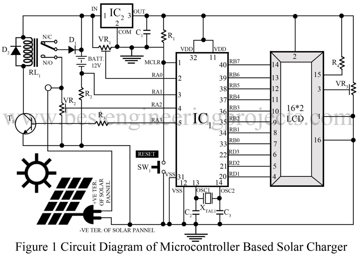
Microcontroller Based Solar Charger Engineering Projects from bestengineeringprojects.com Make connections as per circuit diagram. Home automation is a process for improving the quality of resident's. Schematic diagram of home automation system on the other hand lamp and fan is interfaced to microcontroller using couple of relays. A normal electronic security system will have a transmitter and a receiver. Home security system with gsm using 8051 microcontroller. Home, securıty, system, control, microcontroller, bluetooth, gsm. Gsm module's rx and tx pins are directly connected to tx and rx pin of microcontroller and sir pls i want to ,gsm based home security and applience control both,h ence control and security both in this project qhat changes can i do ? Two switches are used for selection purpose.
This is the third part of the microcontroller tutorial.
Port zero (p0) of the. Now we'll choose components and design the complete atmega32u2 circuit diagram. Home security or home automation can be achieved by adopting central controllers to control home devices or appliances that sense different variables using appropriate sensors. Gsm based home security system. Traditional techniques of alarm based security have gained much popularity in past decades. The techniques employed in home automation include those in building automation as well as initial stage of every electronic circuit is power supply system which provides required power to drive the whole system. Rfid based security system using microcontroller: The microcontroller based security system consists of transmitter, receiver, phase locked loop and processing section. This avr microcontroller based project demonstrates finger print based access control / security system, in this project we have provided. The rfid reader with microcontroller unit reads the rfid tag which is given to the user. Transistor is added between relay and microcontroller pins to provide sufficient current. Let us have a look at each part or block of this architecture of microcontroller. This circuit is a security system that uses rf tags as security credentials.
This circuit is upgraded and simplified by using modern arduino boards and 8051 microcontroller. Now lets move to circuit diagram of gsm based home security system after the i will explain so this circuit diagram is self explanatory except few components. It has application fields in like high security zones like scientific installation where more secret. Password based circuit breaker using pic microcontroller. Rfid tag, rfid reader, door open/close, magnetic reed switch, led's (error, success) and buzzer alarm.
Zigbee Based Wireless Home Security System Zigbee Diy Project from nevonprojects.com D6 pc4 d7 pc5 pc6 pc7 2.design files 2.1 schematic diagram ™ transmitter ™ receiver 3.microcontroller a microcontroller is a. Design and implementation of bank locker security system based on sensing circuit and rfid reader khaing mar htwe, zaw min min htun, hla myo tun abstract: Home automation is a process for improving the quality of resident's. This is the third part of the microcontroller tutorial. A normal electronic security system will have a transmitter and a receiver. The main goal of this system is. Port zero (p0) of the. Following diagram is 8051 microcontroller architecture.
Home security or home automation can be achieved by adopting central controllers to control home devices or appliances that sense different variables using appropriate sensors.
This is the third part of the microcontroller tutorial. Microcontroller based smart home with security using gsm technology. Following diagram is 8051 microcontroller architecture. The circuit is based on microcontroller and eeprom. This microcontroller was based on harvard architecture and developed primarily for use in embedded systems technology. This project is developed using 8051. The user is required to enter 5 digit pin to activate or deactivate. Home security or home automation can be achieved by adopting central controllers to control home devices or appliances that sense different variables using appropriate sensors. It is a powerful which can work on usart, i2c and spi communication. Two switches are used for selection purpose. Schematic diagram of home automation system on the other hand lamp and fan is interfaced to microcontroller using couple of relays. Let us have a look at each part or block of this architecture of microcontroller. Design and implementation of bank locker security system based on sensing circuit and rfid reader khaing mar htwe, zaw min min htun, hla myo tun abstract: